As we all know, wearing a helmet is mandatory in most countries, including India while driving a vehicle, not just because of police fines but to save our own lives. Since it holds such an important position, making it smart would be highly beneficial.
In this Arduino project, we’re turning an ordinary two-wheeler helmet into a Smart Helmet using Arduino Uno and an RF Transmitter & Receiver by adding features like a theft alarm, wear detection, alcohol detection, and drowsiness detection. And the best part is, you don’t need advanced engineering knowledge or complex components to build this project—it's super simple!
Without any further ado, let's get started!
Table of Contents
- Overview
- Components Required
- Smart Helmet Circuit Diagram and Assembly
- Arduino Code for the Smart Helmet
- Transmitter Section
- Receiver Section
- Working of Smart Arduino Helmet
- └ 1st - Theft Detection
- └ 2nd - Wear Detection
- └ 3rd - Sleep Detection
- └ 4th - Alcohol Detection
- Instructions for Proper Functioning of Smart Helmet
- GitHub Repository with Code and Circuit
Overview of the Smart Helmet
In this tutorial, we will build an IoT-based smart helmet with multiple features using simple, regular components. To be clear, the project is split into two parts: the Transmitter (placed in the helmet) and the Receiver (placed in the vehicle). Depending on the features and application, the component list may vary. However, as an overall idea, we will be using an RF transmitter and receiver that operate at 433 MHz. We have built a lot of RF Projects and IoT Projects previously, you can also check them out.
As discussed in the introduction, the features we will be covering are simple yet smart. To be precise, there are four features in total that we will be adding to this project:
Theft Detection
Wear Detection
Alcohol Detection
Drowsiness Detection
Unlike normal drowsiness detection projects, this one uses a special time window logic for drowsiness detection. It ignores normal blinking but tracks sleep signals within a set period. If multiple signals occur within a defined time window or the eyes remain closed for too long, the system detects drowsiness. This smart approach enhances safety with simple yet effective monitoring.
Components Required for Building a Smart Helmet
Since this project has two different circuits (Transmitter and Receiver), I will list the required components for each separately.
Transmitter Side
Arduino UNO R3 - 1
433 MHz RF Transmitter - 1
IR Sensor - 2 (one for wear detection and another for drowsiness detection)
MQ-3 Sensor - 1 (for alcohol detection)
LED & Buzzer - 1 each (for warnings)
Any battery source for powering the setup
Helmet for demo purpose
Breadboard - 1
Connecting wires - required quantity
Receiver Side
Arduino UNO R3 - 1
433 MHz RF Receiver - 1
16x2 LCD Display with I2C Module - 1
1-Channel Relay Module - 1 (for turning the engine on & off)
LED & Buzzer - 1 each (for warnings)
Breadboard - 1
Connecting wires - required quantity
Optional
For demonstration purposes, we will be using a separate BO motor with a separate battery power source.
This completes the required components list. As usual, the list is completely customizable according to your requirements and ideas. You are not limited to the list above.
Before proceeding to the next step, kindly verify the working of each and every component.
With this, let's move to the next step.
Smart Helmet Circuit Diagram and Assembly
First, let's take a look at the transmitter side. The complexity here is that we need to fix the circuit in a mobile and remote place—the helmet. So, simplifying the circuit is most important to make it compact and reliable.
Transmitter Section
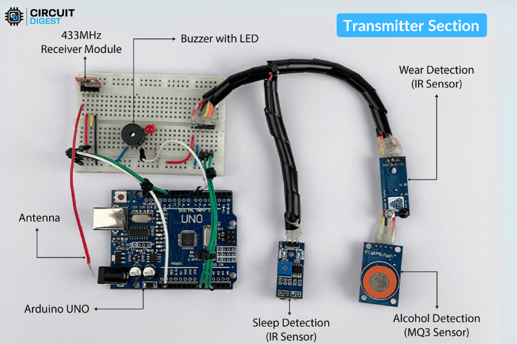
The circuit diagram is simple and easy to understand, but assembling it can be a bit challenging. Below, you can see the circuit diagram for the Smart Helmet transmitter side.

Here, we planned to use three sensors: two IR obstacle detection sensors (for sleep detection and wear detection) and an MQ3 alcohol detection sensor. All three require a 5V DC input, so with the help of some external wires, I made a parallel connection between the VCC and GND of all the sensors, making it a single input. Similarly, I soldered an extra wire at the output of each sensor so that it would be easy to attach to the breadboard with a minimal footprint. If you are a beginner, you can check out our Arduino IR sensor and Arduino MQ3 sensor tutorials to understand more about these sensors and how they work with Arduino.
The length of the wires was carefully calculated while placing all the sensors in their actual positions on the helmet. The sensors’ outputs are connected to the analog input pins as follows:
MQ3 (Alcohol Detection) → A0
Wear Detection Sensor → A1
Sleep Detection Sensor → A2
You can refer to the image below to understand the actual wiring of the sensors in the helmet.
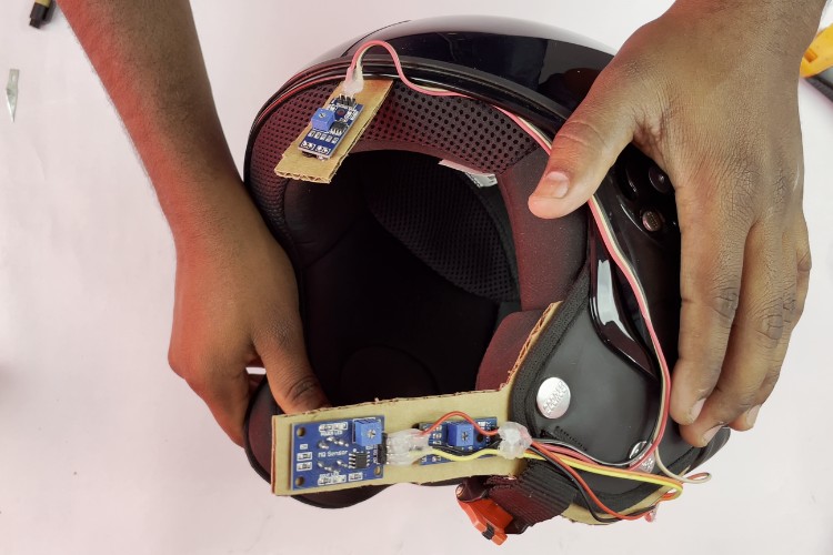
To make the installation simple and efficient, I used an old cardboard box and made appropriate cutouts. The placement of components depends entirely on the type of helmet and specific requirements.
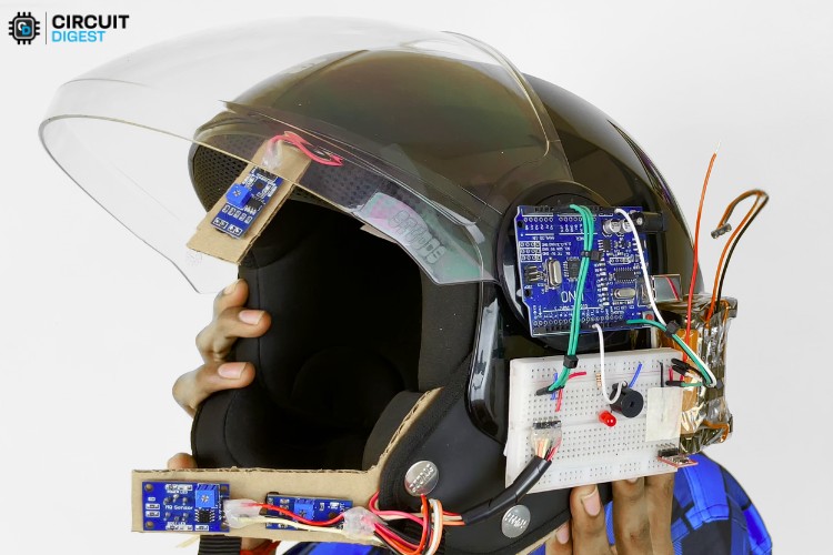
I have used a half-size breadboard for the main circuit connections. Here, I connected the RF transmitter module, LED, buzzer, and all sensor connections. The RF transmitter module was powered with 5V, just like the sensor network.
The 12th pin was connected to the data pin of the transmitter module.
The LED and buzzer were connected to the same I/O pin, pin 7, with a 1KΩ current-limiting resistor.
You can refer to the image below for a clearer view of the circuit connections and placement in the helmet.

For powering the circuit, I used a 2-cell lithium battery.
Finally, coming to the antenna of the transmitter module, I used an online calculator to determine the length of the antenna wire. The approximate value was 17 cm.
Below you can see the assembled image of the circuit connection alone for more clarification
With this, the transmitter part is complete.
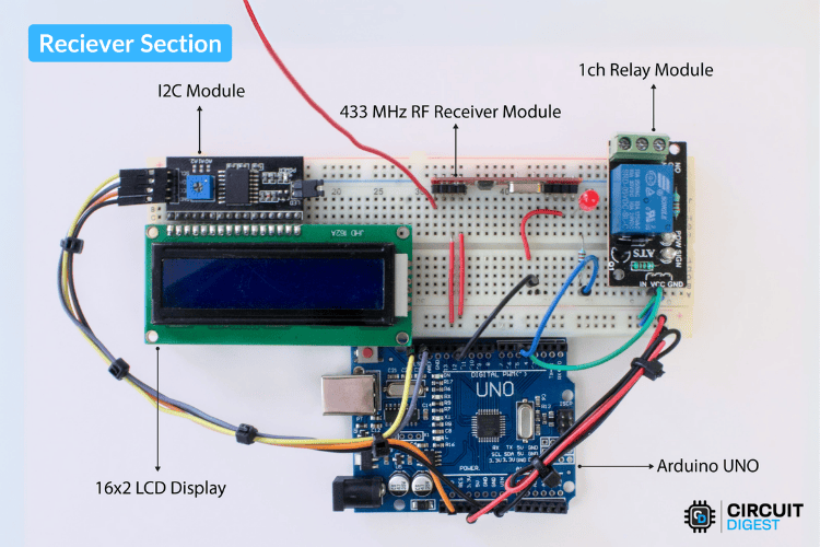
Receiver Section
Now, moving on to the receiver section, which is also a simple circuit. The main components used here are:
LCD display with I2C
Arduino Uno
RF receiver module
Relay module
Buzzer and LED for indication
Below, you can see the circuit diagram of the receiver section. If you want to learn more about these components and how they work with Arduino you can check out our Arduino LCD display, Arduino RF module, and Arduino relay module tutorials.
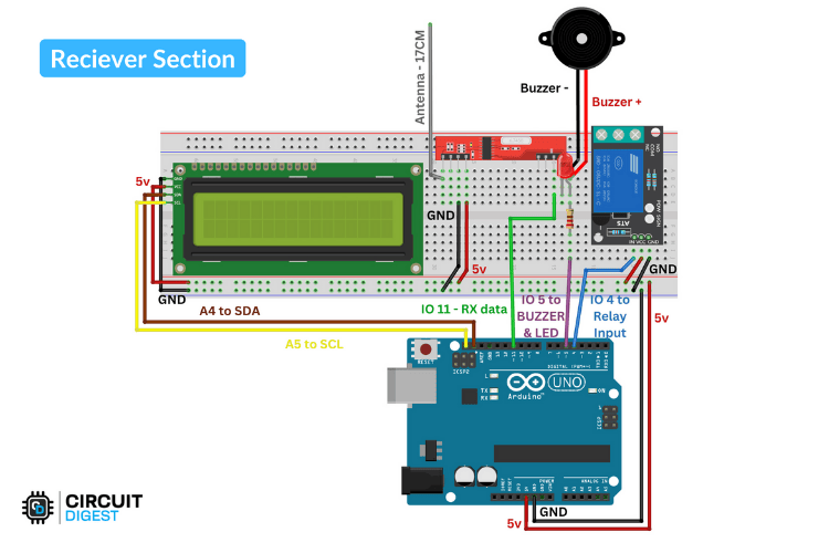
There are a total of four connections from the Arduino I/O pins:
Relay → Pin 4
LED & Buzzer → Pin 5
I2C Display Module → SDA (A4), SCL (A5)
RF Receiver Module → Pin 11 (Data Pin)
All the modules are powered with 5V from the Arduino. Below is the assembled image of the receiver side.
Just like the transmitter side, the receiver also requires an antenna, so I added the same 17 cm wire.
Additionally, I made one extra modification by adding an extra battery and motor to the relay for demonstration purposes. The motor's switch was connected to the NO (Normally Open) and Common terminals of the relay.
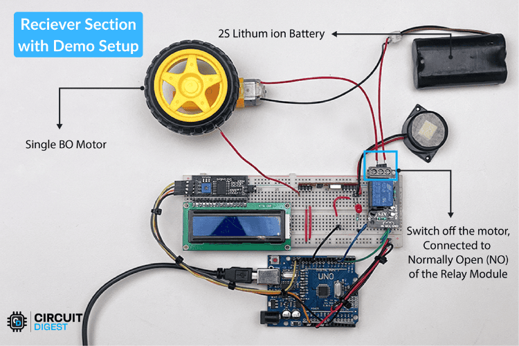
With this, the circuit connection and assembly of both the transmitter and receiver sides are completed.
Next, let's move on to the coding part.
Code for the Smart Helmet
Transmitter Section
Here, the program continuously monitors sensor inputs, evaluates drowsiness based on a time-window logic, and alerts the user if drowsiness is detected. The processed data is transmitted wirelessly at regular intervals.
Libraries Used
RH_ASK – Sub library of RadioHead, that Handles RF communication using the ASK (Amplitude Shift Keying) protocol. (External Library)
SPI – Required by the RadioHead library for low-level communication. (Built-in Library)
Variables and Constants
Debugging
DEBUG_MODE – Enables/disables debug messages in Serial Monitor.
Sensor Pins
alcoholSensorPin = A0 (Reads alcohol sensor input)
wearSensorPin = A1 ( Checks if the helmet is worn)
sleepSensorPin = A2 ( Detects micro-sleep events)
buzzerPin = 7 (Controls the buzzer)
Drowsiness Detection
drowsinessThreshold = 5 (Number of sleep detections required within a time window to confirm drowsiness)
drowsinessTimeWindow = 10000 ms (10 seconds window for evaluating drowsiness)
resetTime = 5000 ms ( Resets drowsiness state if no sleep signals occur within 5 seconds)
sleepTimestamps[] – Stores timestamps of detected sleep signals
sleepIndex – Tracks the circular buffer index
isDrowsy – Stores the current drowsiness status
RF Communication
rf_driver – RF communication object
lastSendTime – Tracks the last transmission time
sendInterval = 50 ms (Sends data every 50 milliseconds)
Setup Function
1.Debug Mode Initialization (if enabled, starts Serial Monitor at 9600 baud rate).
#if DEBUG_MODE
 Serial.begin(9600);  // Start Serial Monitor
 Serial.println("System Initialized...");
#endif
2. RF Module Initialization – Calls rf_driver.init() to set up RF communication.
rf_driver.init();
3. Pin Configuration –
pinMode(INPUT) for all sensor pins.
pinMode(OUTPUT) for the buzzer.
Ensures the buzzer is OFF initially.
pinMode(wearSensorPin, INPUT);
pinMode(alcoholSensorPin, INPUT);
pinMode(sleepSensorPin, INPUT);
pinMode(buzzerPin, OUTPUT);
digitalWrite(buzzerPin, LOW);  // Ensure buzzer is OFF initially
Loop Function
The loop function continuously reads sensor inputs and processes the data for drowsiness detection, buzzer activation, and RF transmission. The alcohol sensor is read to determine alcohol presence, the sleep sensor checks for drowsiness-related signals, and the helmet sensor verifies if the helmet is worn. These values are essential for determining the rider’s condition.
int alcoholLevel = !digitalRead(alcoholSensorPin);
 int sleepSignal = !digitalRead(sleepSensorPin);
 int helmetStatus = !digitalRead(wearSensorPin);
For drowsiness detection, the system uses a circular buffer to store timestamps of detected sleep signals. If a sleep signal is recorded, its timestamp is stored in the buffer. The system then checks if the number of sleep signals within the specified drowsinessTimeWindow exceeds the drowsinessThreshold. If this condition is met, drowsiness is detected, and isDrowsy is set to true. If no sleep signals occur within resetTime, the system resets isDrowsy to false, ensuring normal blinking does not trigger false alarms.
 if (sleepSignal) {
   lastSleepDetectionTime = currentMillis;
   // Store the current timestamp in the circular buffer
   sleepTimestamps[sleepIndex] = currentMillis;
   sleepIndex = (sleepIndex + 1) % drowsinessThreshold;
   // Check if there are 'drowsinessThreshold' sleep detections within 'drowsinessTimeWindow'
   int count = 0;
   for (int i = 0; i < drowsinessThreshold; i++) {
     if (currentMillis - sleepTimestamps[i] <= drowsinessTimeWindow) {
       count++;
     }
   }

   isDrowsy = (count >= drowsinessThreshold);
 }
 // **Reset drowsiness detection if no sleep signals for resetTime**
 if (currentMillis - lastSleepDetectionTime > resetTime) {
   isDrowsy = false;
 }
#if DEBUG_MODE
 Serial.print("Drowsiness Detected: ");
 Serial.println(isDrowsy ? "YES" : "NO");
#endif
The buzzer activates when drowsiness is detected, alerting the rider. If isDrowsy is true, the buzzer turns ON; otherwise, it remains OFF. This immediate feedback helps prevent accidents due to drowsiness.
 // **Activate Buzzer on Drowsiness Detection**
 if (isDrowsy) {
   digitalWrite(buzzerPin, HIGH);  // Turn ON buzzer
 } else {
   digitalWrite(buzzerPin, LOW);   // Turn OFF buzzer
 }
For RF transmission, if the defined sendInterval has elapsed, the system constructs a comma-separated data string containing sensor values. This string is converted into a character array and transmitted wirelessly using rf_driver.send(). This ensures continuous monitoring and communication with external systems.
// **Send data at regular intervals**
 if (currentMillis - lastSendTime >= sendInterval) {
   lastSendTime = currentMillis;
   // Convert sensor values to a formatted string
   String data = String(helmetStatus) + "," + String(alcoholLevel) + "," + String(isDrowsy ? 1 : 0);
   // Convert string to char array for RF transmission
   char msg[data.length() + 1];
   data.toCharArray(msg, data.length() + 1);
   // Send data via RF
   rf_driver.send((uint8_t *)msg, strlen(msg));
   rf_driver.waitPacketSent();
A small delay of 10ms is included at the end of the loop to prevent excessive processing load while maintaining responsiveness.
Next, let's take a look at the receiver code.
Receiver Section
The Receiver System communicates wirelessly using an RF module with the Transmitter System and displays status information on an LCD screen. If the rider is not wearing the helmet or has consumed alcohol, the vehicle ignition is disabled. A buzzer alerts the user in case of drowsiness or safety violations.
Libraries Used
Wire.h: Used for I2C communication, essential for LCD operation.(Built-in Library)
LiquidCrystal_I2C.h: Controls the 16x2 LCD display via the I2C interface. (External Library)
RH_ASK.h: Enables communication with an RF module, using the RadioHead ASK (Amplitude Shift Keying) protocol. (External Library)
SPI.h: Required for RF communication, used internally by RH_ASK. (Built-in Library)
Variables and Constants
Hardware Configuration
ignitionRelay (Pin 4): Controls the vehicle ignition (ON/OFF state).
buzzerPin (Pin 5): Controls the buzzer for alerting the rider.
lcd (0x27, 16, 2): LCD initialization with I2C address 0x27.
rf_driver (2000, 11, 12, 0): Configures the RF module (2000 bps baud rate, RX on pin 11, TX on pin 12).
Data Variables
str_helmet, str_alcohol, str_sleep: Store received sensor values as strings.
helmetStatus, alcoholLevel, sleepStatus: Store integer-converted sensor readings.
engineState: Boolean representing whether the engine should be ON or OFF.
lastReceivedTime: Tracks the last received RF data timestamp.
timeout: Defines the period (5000ms) before showing a system offline message.
page, lastPage: Manage the LCD page display system.
lastPageSwitch, pageInterval: Handle page switching every 3 seconds.
Setup Function
The setup function begins by initializing serial communication at a baud rate of 115200, ensuring efficient data transmission for debugging and monitoring. It then initializes the RF module, enabling wireless communication for receiving helmet, alcohol, and sleep status data. The LCD screen is also set up at this stage, displaying the startup message "Smart Helmet" to indicate that the system is powered on.
lcd.begin();
 lcd.backlight();
 lcd.setCursor(0, 0);
 lcd.print("Smart Helmet");
 delay(1000);
 lcd.clear();
Next, the ignitionRelay and buzzerPin are configured as output pins, allowing the system to control the vehicle ignition and alert mechanisms. By default, the vehicle remains OFF, and the buzzer stays silent to prevent unnecessary alerts during startup. Finally, the system introduces a brief delay before clearing the LCD screen, ensuring a smooth transition into the main loop function.
pinMode(ignitionRelay, OUTPUT);
pinMode(buzzerPin, OUTPUT);
digitalWrite(ignitionRelay, LOW); // Default: Vehicle OFF
digitalWrite(buzzerPin, LOW); // Default: No alert
Loop Function
The loop function is responsible for continuously receiving and processing RF data. It first reads incoming RF signals and extracts key sensor values, including helmet status, alcohol level, and sleep status. These values are received as strings and are converted into integers for further processing.
if (rf_driver.recv(buf, &buflen)) {
   String str_out = String((char*)buf);
   lastReceivedTime = millis(); // Update last received time
   // Extract values from received string
   int comma1 = str_out.indexOf(',');
   int comma2 = str_out.lastIndexOf(',');
   if (comma1 > 0 && comma2 > comma1) {
     str_helmet = str_out.substring(0, comma1);
     str_alcohol = str_out.substring(comma1 + 1, comma2);
     str_sleep = str_out.substring(comma2 + 1);
     helmetStatus = str_helmet.toInt();
     alcoholLevel = str_alcohol.toInt();
     sleepStatus = str_sleep.toInt();
     // Control vehicle ignition based on conditions
     engineState = (helmetStatus && !alcoholLevel);
     digitalWrite(ignitionRelay, engineState);
     // Activate buzzer if sleep or alcohol detected
     digitalWrite(buzzerPin, (sleepStatus || alcoholLevel || page == 99) ? HIGH : LOW);
     Serial.print("Received: ");
     Serial.println(str_out);
   }
 }
Based on the received data, the system controls the vehicle ignition. The engine is allowed to start only if the rider is wearing a helmet and no alcohol is detected. If either condition is not met, the ignition remains off. Additionally, the buzzer is activated if alcohol is detected or the rider shows signs of drowsiness, alerting the user immediately.
To ensure reliability, the code also implements timeout handling. If no data is received for more than five seconds, the system considers itself offline. In this case, the LCD screen displays a "System Offline" message, and the buzzer is triggered to alert the rider.
if (millis() - lastReceivedTime > timeout) {
   if (page != 99) {
     digitalWrite(buzzerPin, HIGH);
     lcd.clear();
     lcd.print("No Data Received");
     lcd.setCursor(0, 1);
     lcd.print("System Offline");
     page = 99;
   }
   return;
 }
The LCD display is managed through a page-switching mechanism. The system cycles through two display pages every three seconds. Page 0 displays the helmet and alcohol status, while Page 1 provides information on the rider’s drowsiness and the engine's state. The display is updated only when necessary to optimize performance and reduce unnecessary screen refreshes.
switch (page) {
   case 0:  // Page 1: Helmet, Alcohol, and Sleep Status
     lcd.setCursor(0, 0);
     lcd.print("Helmet: ");
     lcd.print(helmetStatus == 1 ? "Yes" : "No ");
     lcd.setCursor(0, 1);
     lcd.print("Alcohol: ");
     lcd.print(alcoholLevel == 1 ? "Yes" : "No ");
     break;
   case 1:  // Page 2: Sleep Status and Engine State
     lcd.setCursor(0, 0);
     lcd.print("Sleep: ");
     lcd.print(sleepStatus == 1 ? "Yes" : "No ");
     lcd.setCursor(0, 1);
     lcd.print("Engine: ");
     lcd.print(engineState ? "ON " : "OFF");
     break;
 }
This smart helmet system ensures rider safety by enforcing helmet usage and preventing vehicle ignition in unsafe conditions. The next step is to upload the code and test the system in real-world conditions.
Working of Smart Safety Helmet
Once both the transmitter and receiver sections are uploaded with the appropriate code, we can check their functionality. As usual, for understanding the code, you can check out the flowchart in our GitHub repo to understand the working easily.
In this project, the working is simple. There are a total of four features to check out. I will be adding the detailed working of all four features below.
1st - Theft Detection
The theft detection working is simple. When there is no data received from the transmitter, it means the helmet is too far from the two-wheeler. In this way, we can implement this feature of theft detection.
Below, you can see the theft detection in the smart helmet.
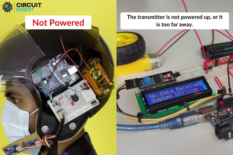
Here, I unplugged the power of the transmitter section so that the receiver can't receive the data. According to our logic, this triggers the theft detection. During this time, the warning LED and buzzer turn ON to alert the surroundings. After reconnecting, it will work properly.
2nd - Wear Detection
For wear detection, we are using data from an IR obstacle sensor placed near the MQ3 sensor at the cheek area. So, while wearing it, it is possible to determine whether the helmet is worn or not.
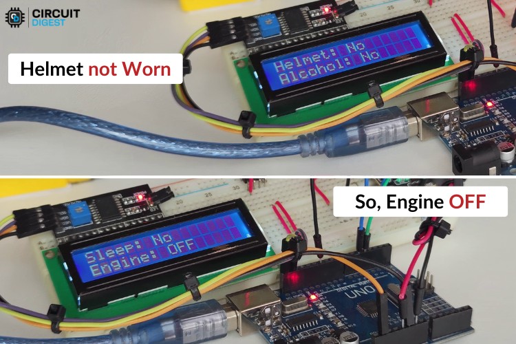
In the above image,, the system is turned ON by connecting the battery to the circuit. But the helmet isn’t worn yet, so we can see "NO" near the helmet indicator on the display.
Once the helmet is worn, the receiver gets the data, triggering the engine to turn ON. You can see that the demo motor connected to the relay of the receiver starts rotating, and the expected variables are updated on the LCD display.
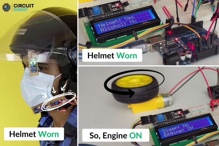
Above, you can see the display result while the person is wearing the helmet and the engine is turned ON.
3rd - Sleep Detection
For this test, we asked the person to avoid blinking, which results in no triggers. But if the blinking time is slow or the eyes remain closed, the trigger starts. The user will then hear the buzzer turn ON along with the warning light, and the status will be displayed on the screen.
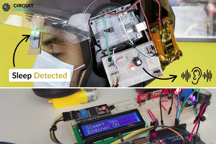
Above, you can see the collage image that describes the process when sleep is detected.
4th - Alcohol Detection
This is also a simple demonstration where we used IsoPropyl Alcohol (IPA) for testing. Similar to wear detection, if the user is detected as having consumed alcohol, the vehicle won’t start.
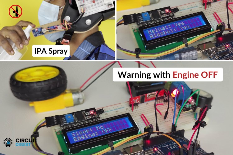
Above, you can see the demonstration of alcohol detection. The engine can only be started once the sensor stops detecting alcohol.
Instructions for Proper Functioning of Smart Helmet
Ensure every sensor’s potentiometer is set properly depending on the environment and conditions. Since every sensor module consists of a comparator circuit made using an OPAMP, it needs to have a proper threshold set using the potentiometer.
The placement of sensors is important to ensure proper working of the system.
GitHub Repository with Code and Circuit


Similar Drowsiness Detection Projects
Explore similar DIY projects that use techniques like facial recognition and heart rate monitoring to detect driver drowsiness and keep you safe with timely alerts on the road.

Arduino based Driver Drowsiness Detection & Alerting System
An Arduino Nano-based system that uses an eye blink sensor to detect driver drowsiness and sounds a buzzer to alert them. A simple, low-cost solution to help prevent drowsiness-related accidents.

Learn how to build a Drowsiness Detection System using Raspberry Pi and Arduino that monitors facial cues, steering behavior, and EEG signals to alert sleepy drivers and prevent road accidents.

iN-Car Drowsiness Detection and Alert System with CAN Bus Integration
Demonstrating drowsiness detection system that uses facial recognition, motion, and ECG sensors to monitor driver alertness. It triggers timely alerts to help prevent accidents caused by drowsiness.
Complete Project Code
/*
 Smart Helmet Reciever code
 Features:
 - Wireless communication via RF module (2000 bps, RX pin 11, TX pin 12)
 - LCD display (I2C Address: 0x27)
 - Ignition control based on helmet status and alcohol detection
 - Buzzer alerts for sleep detection or alcohol presence
 - Automatic page switching on LCD every 3 seconds
 - Timeout alert when no data is received for 5 seconds
*/
#include <Wire.h>
#include <LiquidCrystal_I2C.h>
#include <RH_ASK.h>
#include <SPI.h>
// Initialize LCD display and RF module
LiquidCrystal_I2C lcd(0x27, 16, 2);
RH_ASK rf_driver(2000, 11, 12, 0);
// Define pin connections
const int ignitionRelay = 4;
const int buzzerPin = 5;
// Variables to store received data
String str_helmet = "0", str_alcohol = "0", str_sleep = "0";
int helmetStatus = 0, alcoholLevel = 0, sleepStatus = 0;
bool engineState = false;
// Timeout and page switching variables
unsigned long lastReceivedTime = 0;
const unsigned long timeout = 5000;
int page = 0, lastPage = -1;
unsigned long lastPageSwitch = 0;
const unsigned long pageInterval = 3000;
void setup() {
 Serial.begin(115200); // Initialize serial communication
 rf_driver.init(); // Initialize RF module
 pinMode(ignitionRelay, OUTPUT);
 pinMode(buzzerPin, OUTPUT);
 digitalWrite(ignitionRelay, LOW); // Default: Vehicle OFF
 digitalWrite(buzzerPin, LOW); // Default: No alert
 lcd.begin();
 lcd.backlight();
 lcd.setCursor(0, 0);
 lcd.print("Smart Helmet");
 delay(1000);
 lcd.clear();
}
void loop() {
 uint8_t buf[20];
 uint8_t buflen = sizeof(buf);
 // Check if RF data is received
 if (rf_driver.recv(buf, &buflen)) {
   String str_out = String((char*)buf);
   lastReceivedTime = millis(); // Update last received time
   // Extract values from received string
   int comma1 = str_out.indexOf(',');
   int comma2 = str_out.lastIndexOf(',');
   if (comma1 > 0 && comma2 > comma1) {
     str_helmet = str_out.substring(0, comma1);
     str_alcohol = str_out.substring(comma1 + 1, comma2);
     str_sleep = str_out.substring(comma2 + 1);
     helmetStatus = str_helmet.toInt();
     alcoholLevel = str_alcohol.toInt();
     sleepStatus = str_sleep.toInt();
     // Control vehicle ignition based on conditions
     engineState = (helmetStatus && !alcoholLevel);
     digitalWrite(ignitionRelay, engineState);
     // Activate buzzer if sleep or alcohol detected
     digitalWrite(buzzerPin, (sleepStatus || alcoholLevel || page == 99) ? HIGH : LOW);
     Serial.print("Received: ");
     Serial.println(str_out);
   }
 }
 // Handle timeout if no data received for a set time
 if (millis() - lastReceivedTime > timeout) {
   if (page != 99) {
     digitalWrite(buzzerPin, HIGH);
     lcd.clear();
     lcd.print("No Data Received");
     lcd.setCursor(0, 1);
     lcd.print("System Offline");
     page = 99;
   }
   return;
 }
 // Handle automatic page switching
 if (millis() - lastPageSwitch > pageInterval) {
   lastPageSwitch = millis();
   page = (page + 1) % 2;
   delay(200); // Small delay to prevent rapid switching
 }
 // Clear LCD only when switching pages
 if (page != lastPage) {
   lcd.clear();
   lastPage = page;
 }
 // Display different pages based on current page index
 switch (page) {
   case 0:  // Page 1: Helmet, Alcohol, and Sleep Status
     lcd.setCursor(0, 0);
     lcd.print("Helmet: ");
     lcd.print(helmetStatus == 1 ? "Yes" : "No ");
     lcd.setCursor(0, 1);
     lcd.print("Alcohol: ");
     lcd.print(alcoholLevel == 1 ? "Yes" : "No ");
     break;
   case 1:  // Page 2: Sleep Status and Engine State
     lcd.setCursor(0, 0);
     lcd.print("Sleep: ");
     lcd.print(sleepStatus == 1 ? "Yes" : "No ");
     lcd.setCursor(0, 1);
     lcd.print("Engine: ");
     lcd.print(engineState ? "ON " : "OFF");
     break;
 }
}